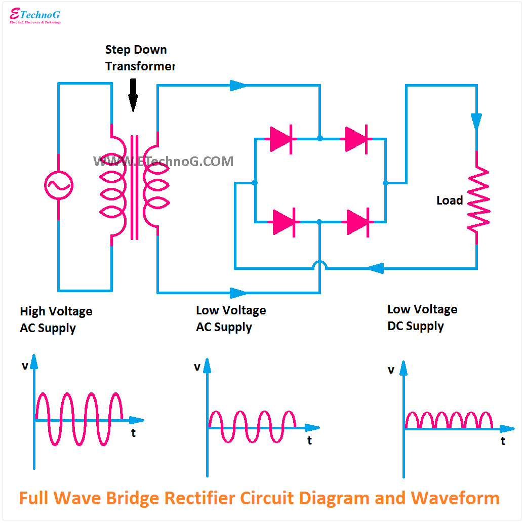
Full Wave Bridge Rectifier Circuit Diagram
Full wave bridge rectifier circuit Full wave rectifier bridge circuit diagram Rectifier bridge circuit wave diagram regulator ic
Full Wave Bridge Rectifier Schematic
Ac to dc rectifier circuit diagram Full-wave bridge rectifier circuit Full wave bridge rectifier schematic
Draw the circuit diagram of a full wave bridge rectifier and explain
Rectifier circuit output principleFull wave bridge rectifier circuit diagram 13+ bridge rectifier circuit diagramHalf wave & full wave rectifier: working principle, circuit diagram.
Full wave bridge rectifierBridge rectifier circuit diagram and waveform Full wave bridge rectifier circuitRectifier wave circuit output waveform input.

Rectifier capacitor waveform prototypes theorycircuit
Rectifier principleFull wave bridge rectifier circuit diagram (4 diagrams) Full wave bridge rectifier circuit diagramFull wave bridge rectifier circuit.
Full wave bridge rectifier circuitRectifier circuit bridge diagram wave working details Rectifier input principle rectifiers theoryFull wave bridge rectifier – circuit diagram and working principle.

Rectifier bridge diagram circuit wave construction principle working
Rectifier wave bridge circuit diagram diode voltage operation peak fig shown its below value inverse when negativeRectifier wave circuit filter without bridge diagram tapped capacitor diodes center four type circuits board using circuitdigest electronic choose two Full wave bridge rectifier circuit diagramRectifier circuit diagram wave waveform output input.
Full wave bridge rectifier – circuit diagram and working principleFull wave bridge rectifier schematic Rectifier circuit diagramBridge rectifier circuit diagram and waveform.

Full wave bridge rectifier – circuit diagram and working principle
Full wave rectifier circuit diagram (center tapped & bridge rectifier)Rectifier circuit diagram Full wave bridge rectifier.
.


